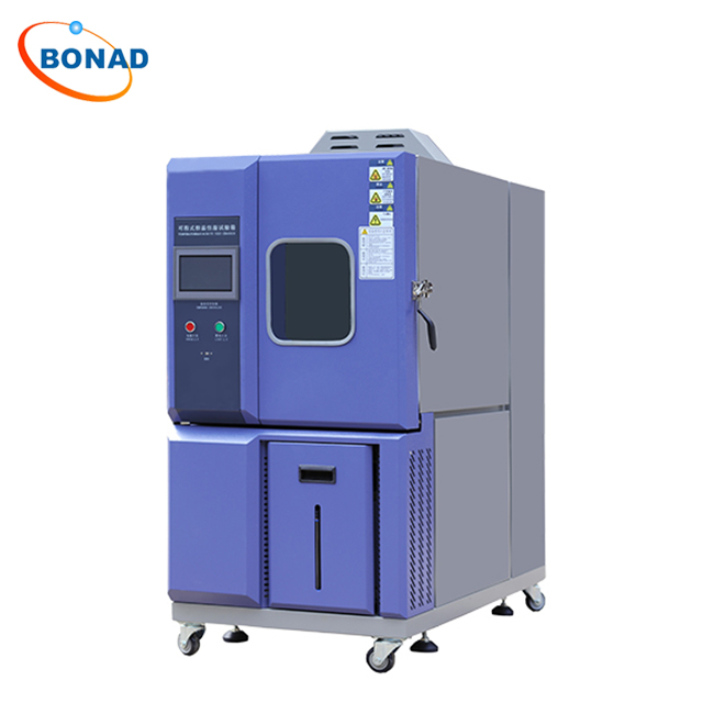
High and low temperature test chambers are crucial devices used for performing reliability tests on industrial products. These chambers simulate extreme temperature environments to evaluate the performance of various products, including electronic devices, automotive parts, aerospace components, and marine weaponry.
Working Principle of High and Low Temperature Test Chambers
The operation of high and low temperature test chambers is primarily based on precise temperature control and regulation. Let's explore the high-temperature control first. Heating is essential to achieve high temperatures within the chamber, which is relatively straightforward. Typically, these chambers use far-infrared nickel-chromium alloy high-speed heating wires for this purpose. The temperature control system employs a PID+SSR system to ensure accurate and efficient energy usage.
For low-temperature operations, increasing the number of heating wires and enhancing the performance of the temperature control software are necessary for rapid heating and achieving high temperatures. Additionally, the refrigeration system is critical for attaining low temperatures. The refrigeration system usually consists of a fully enclosed compressor unit from a French manufacturer, utilizing fluorine refrigerants for cooling. Its operation is based on the reversed Carnot cycle, where the refrigerant is compressed to a higher pressure through the compressor and then exchanges heat with the surrounding medium via the condenser to achieve cooling.
In summary, high and low temperature test chambers transition between extreme temperatures through a synergistic action of temperature balance and control systems. During continuous operation, the control system uses PID automatic calculation to adjust heater output, achieving dynamic balance and ensuring stable chamber operation.

Standard Operating Procedures for High and Low Temperature Test Chambers
1. Power Connection: Connect the power source and switch on the power switch, typically located on the side panel of the control cabinet.
2. Standby Check: Allow the chamber to run for at least 60 seconds and check for any phase sequence alarms.
3. Cooling Water System: Activate the cooling water pump's power switch and open both inlet and outlet valves for cooling water. Ensure that the drain valve is closed before opening. Monitor water pressure gauge readings at both inlet and outlet, ensuring pressure between 0.2~0.6Mpa with a pressure difference greater than 0.2Mpa. Also, ensure water temperature does not exceed 28℃.
4. Humidification Device Setup: If humidity operation is needed, turn on the humidification device's power switch and open the water pipe valve.
5. Setting Test Parameters: Set required temperature and humidity parameters on the chamber's control panel.
6. Start the Test Chamber: After setting test parameters, start the test chamber and enable over-temperature protection.
7. Fault Handling: In case of any alarms during testing, refer to the "Installation and Maintenance Manual" for troubleshooting procedures.
Common Dehumidification Methods in High and Low Temperature Test Chambers
1. Refrigeration Dehumidification Method: This method condenses water vapor in air onto a cold surface, forming water or frost which is then removed from the chamber. However, prolonged testing may cause frost buildup affecting dehumidification efficiency; thus controlling cold surface temperatures above 0℃ is crucial.
2. Solid Desiccant Dehumidification Method: This method absorbs water vapor from air using solid desiccants to achieve dehumidification—ideal for tests requiring lower dew point temperatures around -70℃. Although effective in achieving lower humidity levels due to lower surface water vapor pressure of desiccants, it can be inconvenient requiring specialized equipment.
In special test scenarios like testing internal combustion engines at low temperatures or during operation requiring large air supply for fuel combustion—solid desiccant-based rotary dehumidifiers operating continuously are typically used to prevent excessive frost buildup on evaporators due to new air’s water vapor.
|

