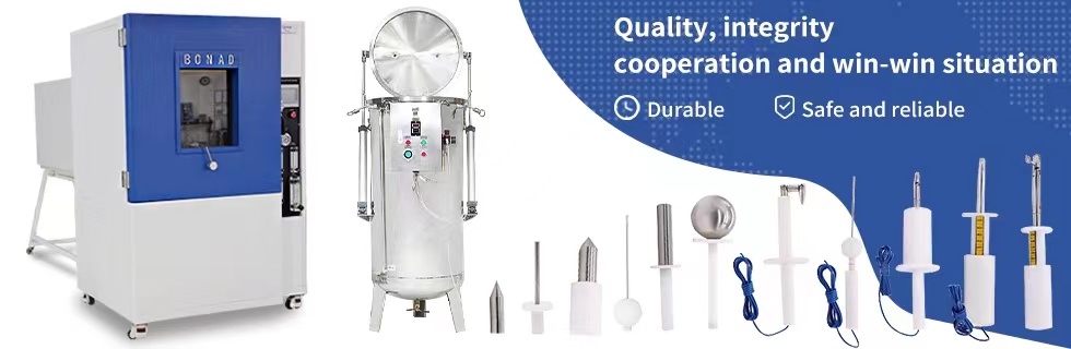
IEC 60695 Glow wire tester
Glow Wire Tester could be applicable to ignition hazard test, combustibility test of electronic industry, home electronic appliance and materials. The glow wire apparatus and common test procedure is to simulate the effect of thermal stressed witch may be produced by heat sources such as glowing elements or overloaded resistors, for short periods, in order to assess the fire hazard by a simulation technique.
Work Principle of PTI glow wire tester
1) After putting the test specimen to the fixture, test specimen could be driven by electronic engine and could go left or right automatically control in the test process.
2) Mount glow wire. Test specimen carriage turns right to glow wire with hammer pulling the carriage in order to keep the force within 1 newton. The force shall be maintained at this value when the glow-wire or the test specimen is moved horizontally one toward the other. The penetration of the tip of the glow-wire into the through the test specimen shall be limited to 7mm.
3) Application time that glow wire tip is applied to the test specimen is controlled by numeric relay beforehand.
4) Ignition time is measured by numeric and controlled by button.
5) Flame extinguishing time is measured by numeric relay and controlled by button.
6) Glow wire temperature is controlled by adjusted glow wire current and measured precisely by Temperature controller.
the main parameter of PTI glow wire tester
1, Glow wire temperature: 500 ~ 1000 ℃ ± 2 ℃adjustable,
2, Heating time: 0-999.9s ± 0.1s,adjustable (normally choose to 30s)
3, Ignition timer: 0-999.9s ± 0.1s, automatically records, manually suspended
4, Flame extinguish time: 0-999.9s ± 0.1s, automatically records, manually suspended
5,Thermocouple: Φ1.0mm sheathed K-type thermocouple.
6, Glow wire: Φ4 mm nickel chromium wire.
7, hot depth: 7mm ± 0.5mm (to maintain the pressure of 1N ± 0.2N hot products into the test)
8, Sample frame speed: about 14mm / s.
9, the pilot background: black background.
10, the pilot process: automatic testing procedures, independent ventilation
11, reference: GB/T5169.10-2006, IEC60695-2-10, UL746A
12, Studio volume: 0.5 cubic
13, equipment size: 1000mm wide × 650mm deep × 1300mm high
14, power supply: AC220V ± 5%, 50Hz, 0.6KVA
This tester is mainly using a adjusted pyrotoxin-the tip of glow wire. Control current controls the application time and operation procedure.
testing standards of Glow-wire Test Apparatus
BND-ZRS Glow-wire Test Apparatus is according to IEC60695-2-1, IEC60695-2-10, IEC60695-2-11, IEC60695-2-12, IEC60695-2-13 (GB/T5169.10, GBT5169.11, GBT5169.12, GB/T5169.13) < Basic testing methods of Glow wire, basic testing methods of Glow wire device>, UL 746A, IEC829, DIN695 and VDE0471.
Operation Procedure of glow wire flammability index
1. Installation
In case of transportation safety, the hammer which is through out the tinsel and tester have been taken out. When receiving test box, please install hammer and tester according to the figures as below.
1) Hammer installation: pull the hammer through the tinsel under the right of the block. The left of tinsel with nut clip into the notch of bottom of carriage.
2) Place the test specimen to the carriage. Put the base plate under the glow-wire. Place the flat smooth wooden board on the base plate if using.
3) The thermocouple is drilled into a pocket hole which is behind the tip of the glow wire. Adjust carefully and do not twist off.
2 Test procedure
1) Press on power and switch on tester. Please offer stable power supply if possible.
2) Mount test specimen.
3) Set up Ta, Ti and Te. (Generally Ta and Ti are 30s and Te is 60s)
4) Adjust 7mm limits: press #18 go right to make glow-wire and test specimen connect to each other. Adjust #23 limits control to start Ta, Ti and Te. Press #15 go left back to left side. Press #16 starts to test, drive engine #24 pulls the carriage #22 to the right up till the carriage contacts to the glow wire #21 and then stop. The drive engine would still continue to go right a little bit and then stop. Measure the distance between the drive engine and carriage by block gauge. It is supposed to be 7mm. If it is not 7mm, calibrate the limit control #23 until it is 7mm. Press #6 stop the test to make carriage back to left side.
5) Heat glow wire: Adjust #7 heating current regulation to the least. Press #8 start to heat; glow-wire’s temperature is rising. Adjust #7 heating current regulation to increase the heated current slow. (The higher current of glow-wire, the higher of the temperature. The temperature would fall down when current is decreasing). The above action would make #5 temperature controller’s temperature practice value meet required value. (Temperature controller has practice value and set value. PV stands for practice value which is shown the temperature value of the tip of glow wire. SV stands for set value which is shown thermocouple’s controlled temperature value. SV is set up to 1000℃ that means if the temperature of the tip of glow-wire is over than 1000℃, heating system will cut off power supply automatically. Therefore, Do not amend the set value but only observe practice value.) When using this tester, the referenced temperature of the tip of glow wire and electric current as following.
|
Temperature of the tip of glow-wire
|
Electric current
|
|
550℃
|
65A~75A
|
|
650℃
|
80A~90A
|
|
750℃
|
95A~105A
|
|
850℃
|
110A~120A
|
|
960℃
|
130A~140A
|
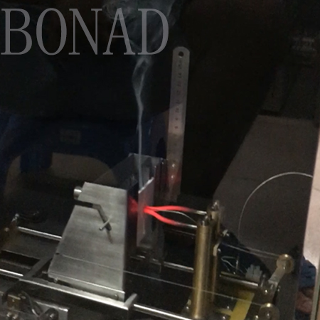
6) Once temperature is up to and keep on the required value and 60 seconds after, you can start testing. Close the tester door, press #16 to start testing. Test carriage drives to the end of right side automatically and then Ta, Te, Ti start the timer. Take attention to the test specimen to see if it catches fire. If it catches fire, press #9 to stop ignition immediately. (Generally, the ignition duration to catch fire is within the applied duration ) And take attention to the test specimen to see if it is extinguished. If so, press #10 to stop extinguishing. (Generally extinguishing duration could be in or out of application duration.) When the heating time is over, the tip of glow wire will cut off power supply and be back to the end of left side automatically.(When heating, the heating current is not changing but the practice temperature of glow wire tip is changing. The temperature could change according to the test specimen which is normal phenomenon.)
7) Take records of Ta, Ti, Te and then press #17 stop testing and anything reposition. Open vent-pipe to eliminate smoke.
8) Press #17 if break off the test. Press #11 if stop heating.
9) Clear up ash and sinter after testing in case of canker.
3. Reference data in normal test process unless others specific.
1) Test specimen size: length is ≥60mm, width is ≥60mm, thickness is 3±0.2mm
2) Test specimen installation: mount test specimen on the fixture. The planar of the surface is vertical to the horizontal level. The tip of the glow-wire is applied to the centre of the planar area of the surface or the thinnest of test specimen with at least 15mm to the top edge.
3) Test specimen quantity: more than 10.
4) Heating time (Ta): the duration of the tip of glow wire is applied to test specimen. Normally it is 30s.
5) Ignition time (Ti): the duration from heating to ignition of test specimen or layer. Normally it is set up to 30s.
6) Flame extinguishing time (Te): the duration from heating to extinguishing test specimen or layer. Normally it is set up to 60s. The formulation should be Te≤Ta+30s. When Ta is equal to 30s, Te should be less than or equal to 60s.
7) Qualified product appraisal: When testing, no flame happens. If it has flame, it should meet requirement as following: 1) Te≤Ta+30s, 2) Apparatus around or wooden board has not got complete combustion. The wrapping tissue should not catch fire.
8) Test result:
a: Test specimen origin, operation method, specific measure, quantity, conditioning.
b: Test method, test times, test layer
c: Heating time(Ta), Ignition time(Ti), Extinguishing time(Te).
d: Glow wire flammability index, Glow wire ignition temperature
|